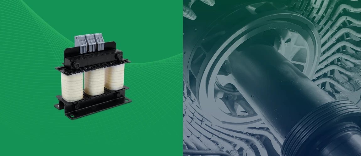
Three Phase dv/dt Reactor
dv/dt Reactors or Load Reactors are inductive devices that play an important role in protecting motor installations. In this blog, we shall be dealing with the various scenarios that might cause motor failure when connected to VFDs, understand the phenomenon of voltage overshoot (or dv/dt) and study how a dv/dt Reactor can help in minimising these failure conditions.
If you missed the first part of the blog series, which is the summary introduction to all the reactors and filters used for Motor and VFD protection, you can find it here https://emisglobal.com/emis/emi-filters-for-vfd-applications/
How can VFD output cause motor failure?
The use of IGBT (Insulated Gate Bipolar Transistors) in VFD has helped to improve VFD performance in several ways – lesser energy loss, lesser requirement for cooling and smaller size footprint of the VFD device, minimised harmonics and reduced audible noise.
However, the VFD is a known source of interference, both on the input and output side. The typical problems that may result on the output side of the VFD are listed below:
- Excessive dv/dt and overvoltage
- Eddy current and displacement current losses
- Electromagnetic Compatibility issues
- Overheating during peak voltage
- Service life and reliability issues with the motor
- Low motor efficiency and power factor
The dv/dt issue or overvoltage is the most important cause of worry.
What is the problem of excessive dv/dt (or Voltage Overshoot)?
In order to minimise losses in the VFD, the switching time or voltage rise time (measured as dv/dt) is much quicker in IGBTs due to the use of Pulse Width Modulation (PWM) technique.
The drive simulates a usable wave form modulated at very fast speeds, at the appropriate duration and polarity, to vary the speed of the electric motor. But as a consequence, the fast switching speed creates a problem for the motor due to excessive dv/dt. This is the measure of the rise time and magnitude of the voltage on the edge of the cycle transitions.
Excessive Dv/dt of over 12 kV/us can be reached at times. However, most motors have a permissible limit of around 1000 V/us. In order to set universal compliance standards, the IEC 60034-17 and IEC 60034-25 standards clearly define the permissible voltage peak limits.
Those fast waveform pulses create the voltage distortion and spikes that can cause damage to the motors insulation system and shorten the motor service life.
While inverter duty motors are designed to tolerate this condition, even the best insulation system will operate better and longer if the distortion is kept to a minimum. The design inductance of a dv/dt reactor minimises the sharp edges and slows down the distortion in the voltage reaching the motor.
Voltage overshoots and voltage peaks can come with high dv /dt values. They can be a problem on their own too. This is because of the fast voltage pulses of the switching frequency. The choke function causes voltage peaks during every switching cycle. The phenomenon is also referred to as line notching.
Lead length between VFD and Motor – why does it matter?
The lead length is generally high between the VFD and motor. There are several practical reasons for this. Motors may be installed outdoors (for instance, inside wells or mines). Whereas VFD is a sensitive electronic device which requires additional care, and is usually kept in clean and dry indoor conditions. Because of this reason, a long length cable is used between them. Another scenario is when several motors on the line are connected to a single drive system such as in the case of conveyor belts.
VFD manufacturers clearly specify the maximum permissible cable length between the VFD and motor in their product specifications, for optimum service life of the motor. These ranges may be between 30-100m. When installed at a longer distance, the motor failure may occur quite frequently.

The reflected wave phenomenon
IGBTs let drives turn voltage on and off at a very high frequency, in the range of 4,000 to 16,000 times a second. As a result, the voltage rise time is very short (< few microseconds).
VFDs today operate via pulse width modulation (PWM), with the inverter producing a continuous train of pulses rather than sinusoidal waveforms. These voltage pulses are transmitted to the motor terminals through the motor cable. When cable lengths are longer, its inductance increases. This causes greater delays in time taken to charge the capacitance in the motor. When the voltage pulses reach the motor, they encounter a higher impedance than in the cable, causing the pulses to be reflected back to the drive. As these reflected waves encounter incoming waves, their values can add, causing higher peak voltage. Longer the cable, greater the reflected wave (or overvoltage). More energy stored in the cable results in a higher over-voltage, which can be extremely damaging to the motor.
Indicators of Voltage Overshoot:
- Rapid Breakdown of Motor Insulation
- Bearing Pitting and Fluting
- Damage to Cables
- Motor Heating, Motor Noise, and Motor Vibration
- Instrumentation Noise
Dv/dt Reactors – Functions and Characteristics

A 3-phase line/load reactor is an inductor wired in series between two points in a power system. It is recommended to mount the dv/dt reactors as close to drive as possible. It is important to select and install output load reactors based on the cable length between the motors and the VFDs.
The addition of a dv/dt reactor to the output of a drive will dampen overshoot peak voltage, reduce motor heating and audible noise, helping to extend the life of the motor.
Other Benefits of dv/dt reactors:
Significant increase of service life of electric motors
High reliability and production up time for mission critical applications
Less interference propagation towards neighbouring equipment or lines
A dv/dt reactor helps to stabilize the current waveform, and act as an impedance between the VFD and the motor. That impedance will both protect the input section of the motor and reduce the harmonic current drawn from the drive output by the motor. By controlling the waveform within permissible limits, the overheating due to excessive voltage spikes is eliminated, thus putting less stress on the motor components.
Dv/dt reactors consist of a steel core which is constructed of electrical grade steel laminations, and copper wound coils on each leg of a three-phase device.

Dv/dt (and line) reactors are classified by their percent impedance (denoted as percent IZ or %IZ), which is the voltage drop due to impedance, at the rated current. This is expressed as a percent of rated voltage.
3 Phase dv/dt Reactors from EMIS

A 3-phase dv/dt Reactor is a set of three separated winding coils in one assembly. It is connected in the VFD output line such that all current flows through the reactor.
EMIS dv/dt reactors are widely used for motors with cable length of around 30 metres. They are compact and cost effective and play a critical role in increasing the motor reliability and service life. The voltage still being PWM pulse pattern shaped generates a lower output current ripple.
Applications
These reactors are extensively used in:
Frequency converter applications, for example, elevators, pumps, conveyor systems or HVAC systems.
Motor Drive application with cable length of around 30m
Machinery comprising of Servo motors
Features
- dv/dt reduction
- Reduction of voltage stress at the motor
- Maximum Continuous Operating Voltage : 400VAC
- Switching frequency : 2 to 16KHz
- Impedance : 0.8% at 400VAC, 50Hz and rated current
- Protection of motor coil insulation from premature aging and
- Destruction
- Easy to install
- Compact Design
- Compliance with Industry standards (EN 61558-2-20,UL 508C)
- Help increase the service life and reliability of the motor
- Keep peak voltage limit under control and prevent overheating
- Reduced EMI to electronic devices installed nearby
- Minimise magnetic coupling of interference and of parasitic earth currents