Passive Harmonic Filters for Inverters – Three Phase Passive harmonic filters from EMIS
AC motors used in industrial environments are connected to an inverter device for speed and torque control. An inverter (also known as frequency converters or variable frequency drives in different contexts)is a power conversion device which converts fixed frequency, fixed voltage input power to a variable frequency, variable voltage power input to an AC induction motor. This conversion does not affect the performance of the motor in any way, it just improves its efficiency and ensures reduction in mechanical wear and tear of the motor.
Since AC motors are one of the largest energy consuming devices in industrial applications all over the world, the prevalence of inverters is also enormous. However, with the growing use of inverters in distributed generation, a critical problem emerges –harmonic distortion. If generated harmonics get injected into the grid, it can cause malfunctioning of sensitive equipment connected on the same line. The use of well-designed harmonic filters can mitigate this critical risk.
What is Harmonic Distortion?
Harmonics are current and voltage waveform distortions in power supply. Harmonics occur in integer multiples of the fundamental (supply) frequency – 50 Hz in India/Europe, 60 Hz in North America.
A distorted waveform creates heat in the power delivery equipment that can cause severe damage to both domestic and industrial equipment using the utility power supply. Harmonics are created due to presence of non-linear loads which draw non-sinusoidal currents from an essentially sinusoidal voltage source. This leads to corruption of the supply voltage in the main power lines.
There are several nonlinear equipment sources that can potentially trigger harmonics in the line, affecting all other connected devices. These devices include rectifiers, inverters, electronic starters and battery chargers, home appliances, SMPS, office automation devices and so on. Since such devices are a dominant part of our industrial and home environment, harmonic distortions are inevitable. Therefore, necessary corrective action has to be taken at the design level itself.

Total harmonic distortion (THD)
It is a measurement that tells you how much of the distortion of a voltage or current is due to harmonics in the signal. THD should typically(not always) be as low as possible. The acceptable threshold of THD is under 10%, and varies according to the application.

The total harmonic distortion for voltage and current are represented as THvD and THiD respectively.
Effects of harmonic distortion
- Distorts the sine wave shape of the fundamental on the grid. Increased Harmonics increases the phase angle difference between Voltage and Current.
- As the grid has protection equipment, harmonics may give false triggers.
- Increases heating losses, torque pulsations.
- Affects life of the equipment connected to the grid.
- Can cause overheating, resulting in a potential fire hazard.
- Can result in irregular fuse operation, capacitor failure, electronic equipment malfunction, flickering lights and telephone interference.
- Voltage Harmonics with high peak values can weaken insulation in cables, windings and capacitors.
- Current Harmonics in motor windings can create Electromagnetic Interference (EMI).
Solutions to eliminate harmonic distortion
There are 5 common design considerations that help to minimize the THD level.
These are:
- Increasing transformer turns ratio – Increasing the turns ratio (n = Np/Ns) increases the reflected voltage. However, this is a high cost solution and increases voltage stress on the transformer.
- Reduce distortion due to Dead Time of the inverter – As the power devices change switching states, a dead time exists. Dead-time is used for sinusoidal pulse width modulation (SPWM) based inverter control. But the effect includes voltage loss and current distortion. Dead time minimisation techniques help in tackling harmonic distortion.
- Using harmonic attenuators – Distortion due to third order harmonics can be minimized by using delta connections as attenuators.
- Installing line reactors – Both AC and DC line reactors can act as harmonic current limiters. AC reactors protect more equipment when installed between the inverter and power source limiting exposure to power system surges and fluctuations.
- Adding Harmonic filters at the input – Harmonic Filters are basically LCR circuits which are capable of eliminating excess currents. THD could be reduced to as low as 5-10 % % using harmonic filters.
Out of the solutions discussed above, some are suitable only to be used with specific load conditions and may not be cost effective. The simplest and most effective solution therefore is to use an Harmonic filter.
Harmonic Filters are capable of eliminating excess currents in 2 ways:
- Prevent excess current generated by a load (appliance) from being propagated to the supply line
- Remove excess current in the line before it reaches the load
There are 2 types of harmonic filters – passive harmonic filters and active harmonic filters.
Active harmonic filters
They consist of combinations of LCR circuits along with power electronic circuitry. They operate by injecting in the opposite direction, the harmonics generated by the load. This reduces the harmonics in the line. They are very effective for systems that have multiple loads like UPS, VFD and DC drives. However, their initial and running costs are very high. It is also difficult to construct a large-rated current source with a rapid current response. They have higher space requirements which makes installation bulky. And while designing the overall circuit, filter modelling and control scheme is very complex.
Passive harmonic filters
On the other hand, offer a rugged, inexpensive, low maintenance option. They are typically L-C filters installed in a shunt arrangement on the lineside of the inverter. They are tuned to resonate at a single frequency or through a band of frequencies. They could be tuned somewhat below the 5th harmonic,which is the largest component of harmonic distortion. A significant amount of 7th harmonic distortion will also be absorbed. Additional Filters tuned to higher order harmonics may also be used.
Let us discuss these filters in greater detail.
How do passive harmonic filters solve the problem?
Passive Harmonic Filters are designed to provide an alternate path for the harmonic currents and thus keep the main supply lines close to the fundamental frequency. These filters work by exhibiting different impedance values at the resonant frequency. As such, passive shunt filters are designed to be capacitive at the fundamental frequency. For every harmonic current, a separate Harmonic Filter stage has to be added.
In high impedance applications, the filter is connected in series with the load and blocks the harmonic currents. In low impedance applications, the filter is connected in parallel with the load. All the harmonic current specific to a specific harmonic will flow through this shunt filter that can then be grounded. This completely prevents a specific harmonic current from entering a system.

Filter tuning is necessary to reduce harmonic voltage and current distortion, in order to meet the required harmonic performance. The filter will typically be tuned to the lower frequency of the most significant harmonic. However, it is safe to tune the filter between 3 to 15% below the desired frequency to provide sufficient harmonic filtering, and also to allow room for possible filter detuning. Harmonic filter performance across the whole frequency spectrum, at the filter location side (for both normal and contingency conditions) should be considered.
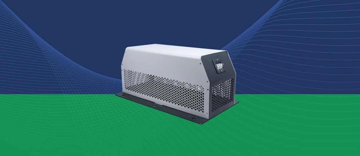
Passive Harmonic Filters from EMIS

Three Phase Passive harmonic filters from EMIS are designed and manufactured to provide an economical and sturdy solution for harmonic mitigation in power systems. These filters effectively maintain THID 5% in compliance with current and voltage requirements of IEEE 519.
Passive harmonic filters being a harmonic absorption type, absorbs the harmonics from both downstream as well as upstream within its range. Thus they prevent the current harmonic from circulating and getting absorbed within the equipment and also stop it from flowing back to the upstream power grid.
They are effective in suppressing harmonic currents and decreasing voltage distortion occurring in the sensitive parts of the Power system. Their primary advantages include:
- Consistently maintain THD under 5%
- Rugged, low cost, low maintenance
- Very effective in reducing losses
- Prevents overheating of components
- Prevents transformer failures
- Eliminates nuisance tripping of circuit breakers
- High attenuation of individual harmonics
- Help in the power factor correction
- Specifications and standards compliance with UL 61800-5-1, IEEE-519
Apart from application in inverter systems, Passive harmonic filters can also be used in various kinds of adjustable speed drive systems, SMPS, DC chargers, UPS, power grids, pumps and fan applications, HVAC, and other industrial automation systems.
EMIS Passive Harmonic Filter – Technical Specifications

EMIS INDIA is a leading service provider of Electromagnetic Compatibility (EMC) and Electromagnetic Interference (EMI) engineering and compliance services. Apart from comprehensive EMI/EMC testing facilities, we also offer expert consultancy support for engineering, design analysis and technical training. Our endeavor is to provide our customers all EMI related solutions under one roof.
With the backing of a strong design team and an NABL accredited in-house testing facility, EMIS can offer custom harmonic filter solutions to your design challenges with ease.
Feel free to get in touch with us. We would love to hear from you. For Custom EMI FILTERS SOLUTIONS please do contact us.
Further Reading – Dynamic Braking Resistor is another component that plays a critical part in the proper functioning of inverters. Read about the role of Dynamic Braking Resistors in VFD applications in our blogs – https://www.kwk-resistors.in/the-role-of-dynamic-braking-resistors-in-vfd/
Explore the Dynamic Braking Resistor product range from KWK Resistors at https://www.kwk-resistors.in/